- Dedicated timing systems that use stand-alone cabling and repeaters.
- Networked timing systems that use Ethernet networking cables and switches shared with other automation applications.
1.1. Dedicated timing systems
Time synchronisation systems in substations have historically used a separate distribution system with its own cabling (coaxial, twisted pair or fibre-optic). Two common methods in use are:- IRIG-B time code, conveying time and date information along with synchronisation pulses; and
- 1 Pulse Per Second (1-PPS), which is a very accurate synchronisation pulse that has no time or date information.
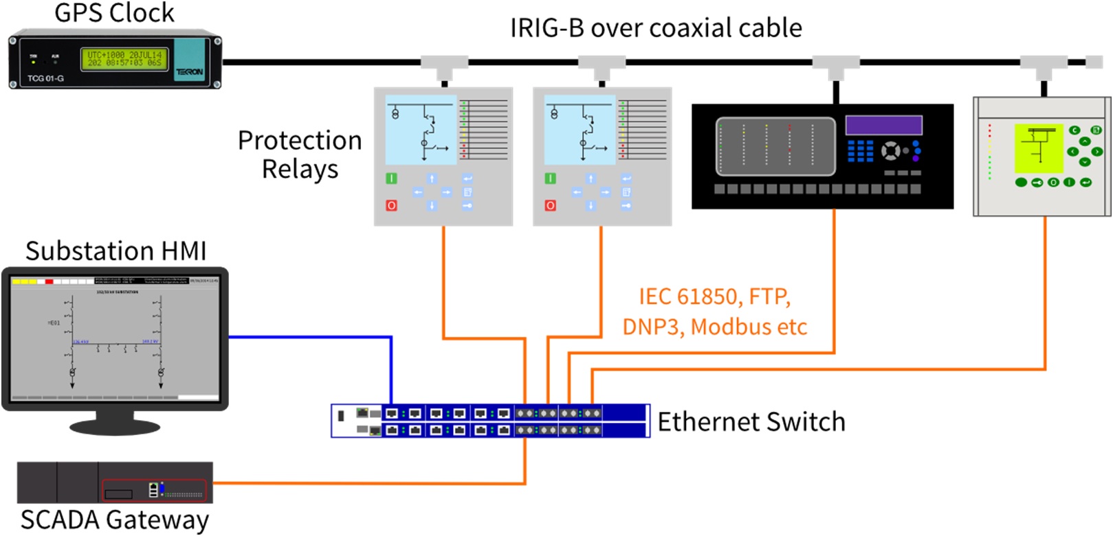
Figure 1: Illustration of separate timing and communication networks in a substation automation system.
1.1.1. IRIG-B
The time synchronisation method most commonly used in substations is the IRIG-B time code, which uses a dedicated distribution network. This time code can be transmitted as raw pulses over copper cables (coaxial or twisted pair) and fibre-optic cables, or as an amplitude modulated (AM) 1 kHz carrier over coaxial cable. IRIG-B has been extended over the years, primarily by IEEE standards for synchrophasors (IEEE Std 1344-1995, IEEE Std C37.118-2005, and most recently IEEE Std C37.118.1-2011). These extensions provide information such as year, time zone offset from Coordinated Universal Time (UTC), daylight saving (Summer) time, and time quality that are essential for substation automation. Unmodulated IRIG-B is capable of sub-microsecond accuracy, however many client devices are limited to millisecond accuracy because of their designs. IRIG-B has a number of options for how the time code is formatted and transmitted. Unfortunately the time synchronisation requirements of the various vendors of substation equipment are sometimes mutually exclusive and cannot be met with one IRIG-B signal. Such differences include whether modulated or unmodulated signals are used, and whether the time is referenced to local time or to Coordinated Universal Time (UTC). The various “flavours” of IRIG-B are known by code values, for example:- B003: pulse width code (unmodulated), no extensions for year or IEEE extensions;
- B004: pulse width code (unmodulated), extensions for year and IEEE extensions;
- B124: amplitude modulated on 1 kHz carrier, extensions for year and IEEE extensions.
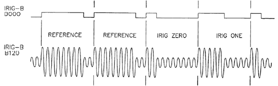
Figure 2: IRIG-B specification for the start of message reference and the data pulses (“0” and “1”) for unmodulated and modulated signals.
Client devices, such as protection relays, need to be configured to match the master clock: UTC vs local time, fixed time zone fixed or set by IEEE extensions and so forth. The flexibility of configuration of protection relays varies significantly, even with protection relays from the same manufacturer. Some protection relays can be configured to accept almost all IRIG-B time codes, but many are limited in their flexibility. Other challenges faced by substation designers when using IRIG-B include: the burden (loading) on the time distribution network, transmission line termination, immunity to noise, galvanic isolation and wiring maintenance. The output capability of master clocks ranges from 18 mA to 150 mA, but each make and model of protection relay presents a different load (typically 5 mA to 10 mA) to the master clock. This complicates the timing design with a moderate to large number of protection relays, such as in distribution or industrial substations with medium voltage (6.6 kV to 33 kV) metal-clad switchgear.1.1.2. One Pulse per Second (1-PPS)
One pulse per second (1-PPS) can be used to provide an accurate synchronisation reference, but does not include “time of day” information. This is sufficient for sampled value process bus applications at present, but time of day information is likely to be required in the future for event time stamping or cryptographic message authentication (to prevent replay attacks). The 1-PPS specification most commonly used for synchronising signals in substations comes from IEC 60044-8, and is referred to by IEC 61850-9-2 process bus implementation guideline commonly referred to as “9-2 Light Edition”. The draft IEC 61869-9 standard for merging unit communication retains 1-PPS over fibre-optic cable as an option for time synchronisation. Figure 3 illustrates the 1-PPS pulse specification. The rise and fall time (tf) between the 10% and 90% levels must be less than 200 ns, and the high time (th) must be between 10 µs and 500 ms (measured at the 50% level).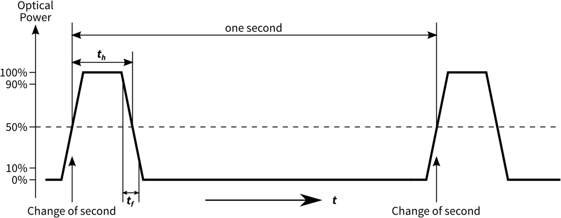
Figure 3: Graphical representation of 1-PPS signal specification.
1-PPS requires a dedicated distribution network, which can use metallic (coaxial or twisted pair) or fibre-optic (multi-mode or single-mode) cables.1.1.3. Distribution and propagation delay
Distribution of IRIG-B and 1-PPS signals using electrical means is simpler than with fibre-optics since multi-drop connections can be used (provided the loading of the source is within limits), but this could result in potential rise between panels. Optical distribution ensures galvanic isolation and eliminates inductive or capacitive interference, but dedicated distribution repeaters are required to split the signal for each protection relay. The 9-2LE guideline for IEC 61850-9-2 requires time synchronisation to be performed using fibre-optic cable. This in turn requires the use of a pulse distributor or a clock with multiple outputs if there is more than one merging unit. The propagation delay through copper and fibre-optic cables is approximately 5 ns per metre. This can become significant with extended cable runs and may require compensation by the connected devices. The 9-2LE guideline sets a limit of 2 µs “error” before compensation is required. This would result from approximately 400 m of cable, and many large transmission substations will have signal cable lengths in excess of this. Compensation is a manual process that requires specific cable lengths distribution repeater delays to be known for each connected device. A detailed study of propagation delay and how 1-PPS, IRIG-B and PTP compare can be found in Reference 1.1.2. Networked timing systems
The Ethernet networks now widely used for substation automation systems can be used to synchronise the internal clocks of devices throughout a substation. This has the advantage of not requiring additional cabling, but does require support for suitable protocols by the various protection relays, power quality meters and other such devices. Two network-based protocols are commonly used: the Network Time Protocol (NTP), and the Precision Time Protocol (PTP). Both protocols, when used in substations, work through the exchange of messages over Ethernet. NTP and PTP can compensate for propagation delay through bidirectional communication. NTP is a more established standard and is widely used, but PTP offers greater performance through the use of special networking hardware. The topology, shown in Figure 4, is the same for NTP and PTP.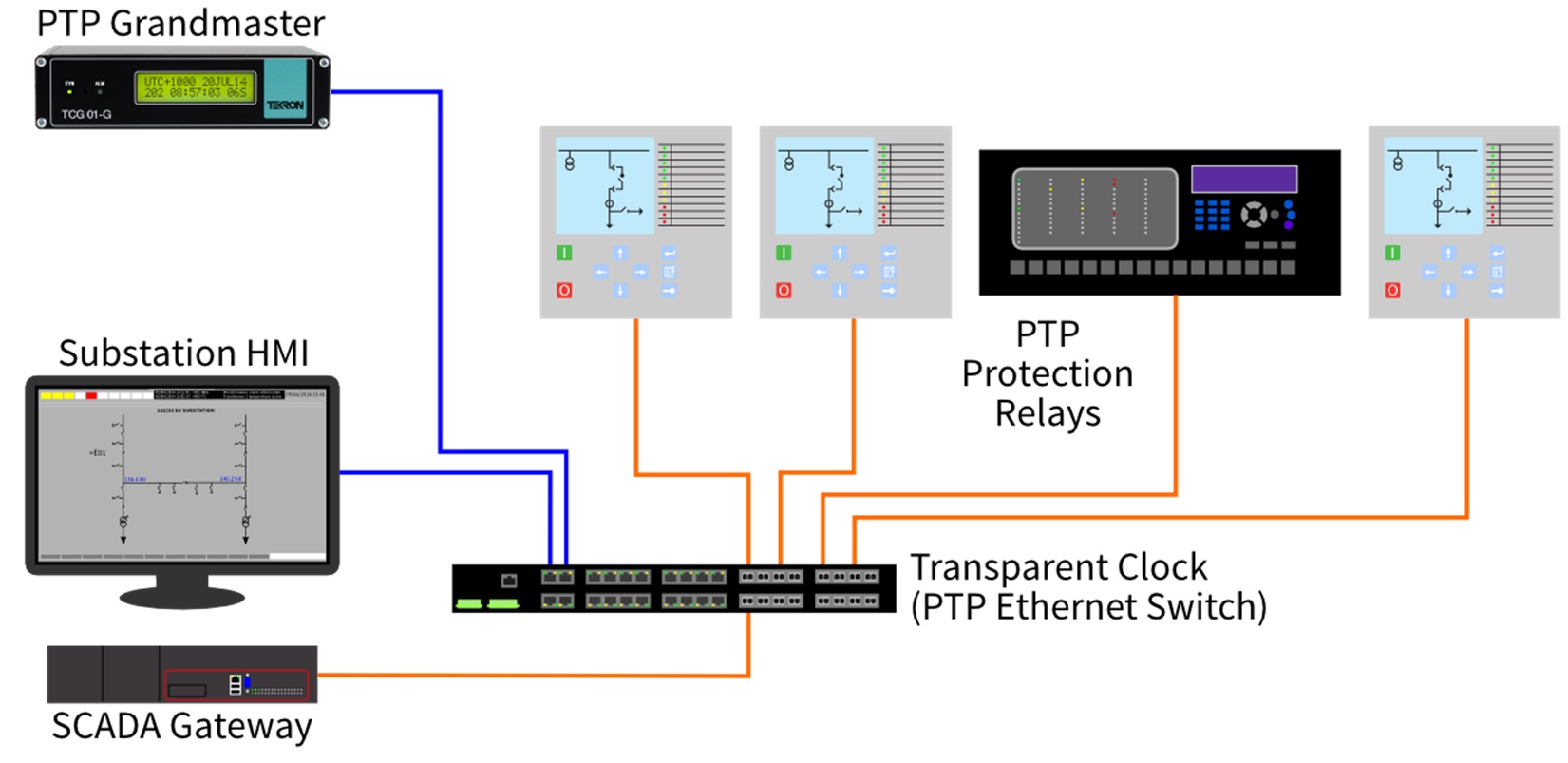
Figure 4: Network topology for NTP and PTP time synchronisation. PTP requires specific types of Ethernet switch, but NTP does not.
Both networked protocols support multiple master clocks, which improves redundancy and reliability of a substation time synchronisation system. In addition, multiple master clocks allows maintenance to take place without taking the timing system (and any dependent protection equipment) out of service.1.2.1. Network Time Protocol (NTP)
In recent years the Network Time Protocol (NTP) running over Ethernet networks has been adopted for substation use.The combination of commercially available NTP servers (clocks) and clients (protection relays) can achieve accuracies of 1-4 ms, but this requires care to be taken in the design of the Ethernet network to minimise packet delay variation. A significant advantage of NTP over IRIG-B for general purpose time synchronisation is time is always transmitted with respect to UTC. This fits with standards such as IEC 61850 and IEEE Std 1815 (DNP3) that require event time stamps to be transmitted using UTC. If it is desired to display local time on the front panel of a protection relay then the local offset to UTC must be manually configured, along with any applicable Daylight Saving transition dates. NTP supports the simultaneous use of multiple master clocks by a client for more accurate and reliable operation. Unfortunately NTP does not achieve the microsecond-level accuracy required for synchrophasors and sampled value process buses.1.2.2. Precision Time Protocol (PTP)
IEEE Std 1588-2008 specifies the second generation of PTP, which is also known as “PTPv2” or “1588v2”. This is capable of very accurate time synchronisation by using special Ethernet hardware that records the exact time a PTP synchronisation message is received at the Ethernet card. This information can compensate for the uncertainty introduced by real time operating systems and other processing delays in both the synchronisation master and the devices that are to be synchronised. The time-stamping hardware does not affect the operation of any other protocols running over Ethernet, and so the same port can be used for IEC 61850, DNP3, IEC 60870-5-104, Modbus/IP and other substation automation protocols. The PTP-specific hardware does marginally increase the cost of Ethernet switches. Native support for PTP is only available in the latest generation of protection relays, and may be an option to be specified at the time of order (depending on the vendor). PTP supports multiple master-capable clocks, but these vote amongst themselves to choose a single clock to be the “grandmaster”. If the grandmaster fails or suffers degraded performance any other master-capable clock on the network will step up to be the grandmaster if it has better accuracy. The time required for this does vary, however if PTP settings (known as a “profile”) optimised for the power industry are used this is usually less than 5 seconds. 2. Introduction to the Precision Time Protocol The Precision Time Protocol is extremely flexible and can be used for a range of time synchronisation applications, with the accuracies of 10 ns achievable with commercially available networking equipment. Extra accuracy was achieved with PTPv2 with the introduction a special type of Ethernet switch called a “transparent clock”. Transparent clocks measure the “residence time” of synchronising messages. This is the time taken for an Ethernet frame to transit the switch, which will vary with network load, and pass it on to downstream devices. This compensates for switch latency due to other network traffic and significantly improves the performance of PTP when a shared Ethernet network is used. The use of transparent clocks means that PTP network traffic does not need to be prioritised over other traffic, simplifying the network design.2.1. PTP terminology
IEEE Std 1588-2008 defines a number of terms for PTP time synchronisation systems. The key terms are:- grandmaster clock: the clock that is the ultimate source of time for synchronisation using PTP, and usually has a GPS (or other satellite system) receiver built in.
- master clock: a clock that is the source of time that other clocks on the network synchronise to.
- slave clock: the end-user of PTP, which may be a protection relay with native support for PTP or a translation device (such as Tekron’s PTP Translator) that generates a legacy time synchronisation signal such as IRIG-B or 1-PPS.
- transparent clock: an Ethernet switch that measures the time taken for a PTP synchronisation message to transit the device and provides this information to clocks receiving the PTP event message.
- boundary clock: a clock that has multiple PTP ports and may serve as a source of time, i.e. be a slave clock to an upstream source and a master clock to downstream devices.
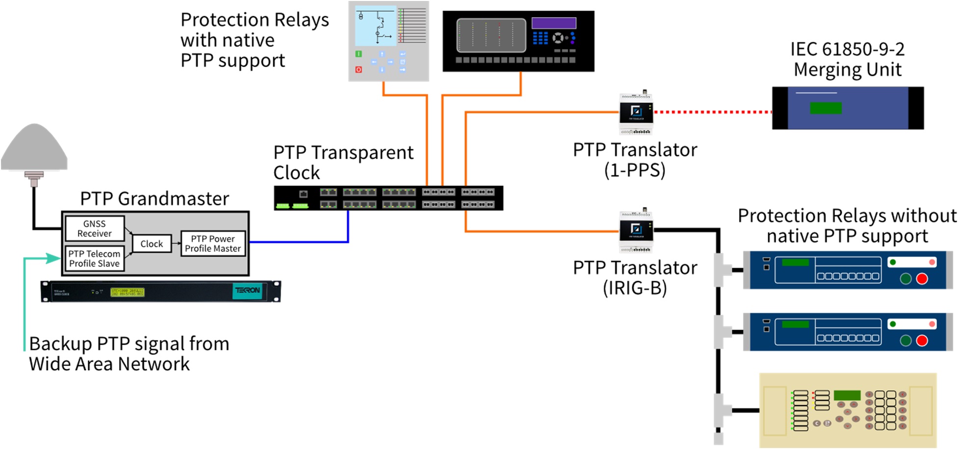
Figure 5: PTP network with a master clock, transparent clock/switch and range of slave clock devices.
2.2. “One-step” and “two-step” operation
PTP relies on knowing exactly when a PTP Sync message (this is the primary message that transfers time) is transmitted and when it is received by the Ethernet interfaces of slave clocks. The exact time a message is sent is not known until it is sent. The special time-stamping hardware in an Ethernet interface that supports PTP then makes this information available to the host CPU in the grandmaster. A Follow Up message is sent that conveys this precise time-stamp to all the client devices. Transparent clocks add their estimate of delays through the network into the “correction” field of the Follow Up message. The combination of Sync and Follow Up messages is called “two step” operation. PTPv2 introduced support for Ethernet hardware that could modify a PTP message on the fly, updating the accurate time-stamp as it was transmitted. This mode of operation avoids the need for Follow Up messages, and is called “one step” operation. A one step grandmaster clock transmits the precise time stamp in the Sync message and transparent clocks provide network delay estimates in the correction for of the Sync message rather than in the Follow Up message. This reduces network traffic, but does require more sophisticated Ethernet hardware PTP systems may include a combination of one-step and two-step grandmaster clocks, and a combination of one-step and two-step transparent clocks. Slave clocks will need to take into account the correction information that has been inserted directly into Sync messages by one step transparent clocks and the updated information sent in Follow Up messages by two step transparent clocks.2.3. The PTP Power System Profile
The PTP standard allows for a number of options, and as with IRIG-B, some options are mutually exclusive. PTPv2 introduced the concept of “profiles” that restrict the available options and may mandate certain features for specific applications. The power industry has a profile, IEEE Std C37.238-2011, that provides a set of optimised parameters and minimal options to deliver accuracy better than 1 µs with network topologies typically found in substation automation systems. This “Power Profile” also defines a Management Information Base (MIB) for the Simple Network Management Protocol (SNMP) that allows key parameters of Power Profile devices to be monitored with industry standard network management tools. The “health” and performance of a time synchronisation system can be monitored in real-time, with alerts raised if there are any issues or abnormalities. This profile incorporates performance criteria for transparent clocks that require no more than 50 ns of error be introduced by each transparent clock. This is to ensure that the 1 µs performance target is met with 16 Ethernet switches (e.g. a ring network topology), while allowing for up to 200 ns of GPS clock error. This covers most substation networks that use a ring (as opposed to star) topology. The Power Profile requires that “peer to peer” transparent clocks be used for all Ethernet switching of PTP messages, and that all messages transmitted using multicast “layer 2” Ethernet frames. “Peer to peer” means that each PTP device exchanges messages with its neighbour to measure the path delay between them, rather than each slave clock communicating directly with the active grandmaster clock. The overall network delay is calculated by adding together the path delays and switch residence times between the grandmaster and each slave clock. This has two benefits:- The network traffic seen by the grandmaster clock does not increase as the network gets larger. The grandmaster only communicates bidirectionally with the Ethernet switch (transparent clock or boundary clock) that it is connected to.
- The PTP system automatically compensates if a network link fails and an alternative path is used. Path delays are measured on all network links, even those that are blocked to normal traffic by spanning tree protocols.
2.4. PTP Messages
PTP, when used with the Power System Profile, uses four classes of message to perform time synchronisation. These are:- Sync messages. These contain the time value from the master clock in the form of the number of seconds and nanoseconds since midnight on 1 January 1970.
- Peer Delay messages. These are exchanged between neighbours to estimate the propagation delay of each path between devices. The Peer Delay mechanism uses two or three separate message types to measure the propagation delay (depending on one-step or two-step operation).
- Follow Up messages. These contain the precise time stamp of when the previous Sync message was sent, along with Correction information. The Correction is the sum of the transparent clock residence times and propagation delays been the grandmaster and that point in the network,and is represented as nanoseconds and fractions of nanoseconds.
- Announce messages. These are information messages transmitted by the grandmaster that provide details of time accuracy of the reference (e.g. GPS receiver) and other PTP protocol information.
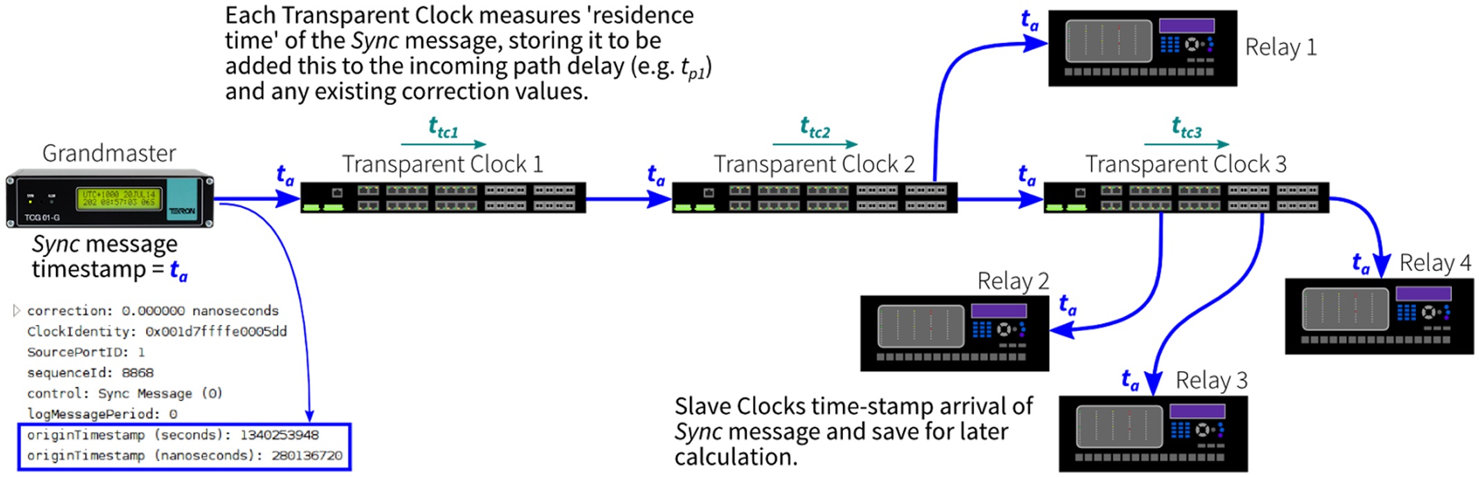
Figure 6: Graphical representation of Sync message travelling through a PTP network.
Peer Delay (Peer Delay Request, Peer Delay Response and Peer Delay Follow Up) messages are exchanged between neighbours, and are not passed on.
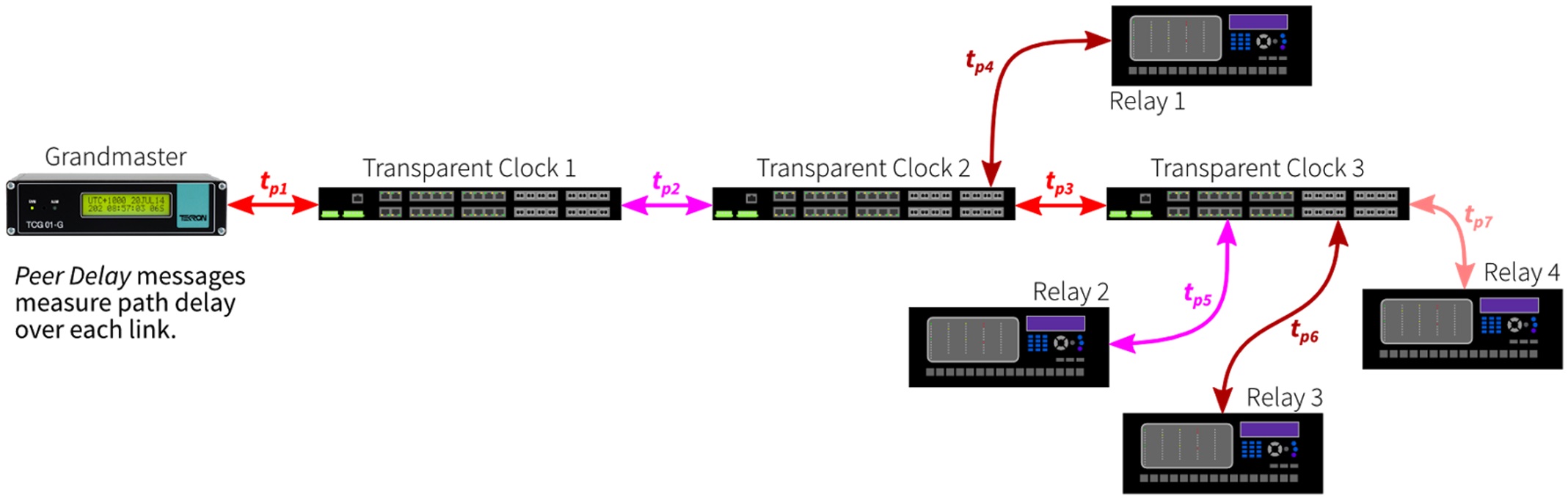
Figure 7: Peer Delay messages are exchanged across each link in the network and are not propagated.
Each transparent clock records the propagation delay of links between itself and it's immediate peers. As a Sync message passes through a transparent clock, the clock calculates a local correction value by adding the propagation delay of the link the message arrived on and the residence time of the message within the clock. This local correction value is then added to correction field of the corresponding Follow Up message. When the messages arrive at the slave clock it adds it's recorded link propagation delay to the correction value which then represents the total time taken for the sync message to travel from the Master to the slave, the path delay. Because the total path delay value is contributed to by each component in the path the sync message takes, the peer-to-peer mechanism used in the Power Profile is very responsive to changes in network topology. It is important to note that while the Follow Up messages may look identical, they will be different at each point in the network. Transparent clocks alter the contents of the message while retaining the original source address of the grandmaster. In Figure 8 tb is the actual time the Sync message left the grandmaster clock and will be close, but not identical, to ta. Each slave clocks knows when it received the Sync message, and by using the precise time stamp and correction information can compensate for variable network delays.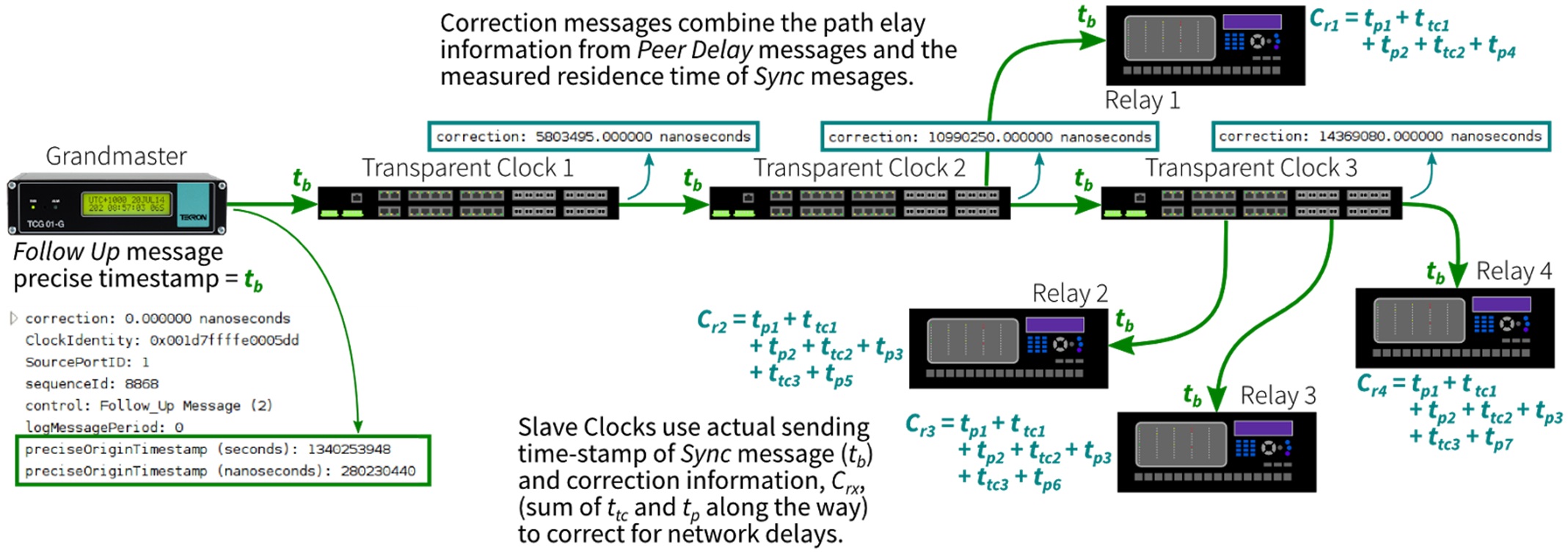
Figure 8: Follow Up messages contain information updated by transparent clocks in the network. Follow Up messages will differ throughout the network, reflecting the different network delays to each node.
2.5. Benefits and issues resulting from PTP and the Power Profile
The Power Profile provides a number of significant benefits for substation automation systems:- Synchronisation accuracy is not affected by other network traffic, provided PTP messages are not lost due to overloading. This allows the same network infrastructure to be used for PTP and for synchrophasors, sampled value process buses, IEC 61850 (GOOSE and/or MMS), DNP3 and so forth.
- PTP messaging rates have been optimised to meet the 1 µs performance requirement of power system applications without placing excessive traffic on the shared network, or requiring overly complex slave clocks.
- Fibre-optic or twisted pair Ethernet can be used, and it is a matter of selecting Ethernet switches with the appropriate port configuration.
- A single time reference is used, so there are no configuration issues regarding UTC or local time. All Power Profile devices use International Atomic Time (TAI), which avoids leap seconds and daylight saving time issues.
- The Power Profile transmits the local time offset, so there is no need to configure the local time zone on protection relays. In addition, any changes to the dates of operation of daylight saving time only need to be made to the grandmaster rather than to every protection relay. The mechanism used is defined in IEEE Std 1588, so is compatible with devices that may not support the Power Profile.
- Redundant grandmaster clocks can be used, with automatic failover if the active grandmaster suffers loss of network connectivity or degradation of performance.
- Protocols that enable redundant Ethernet connections, such as Rapid Spanning Tree Protocol (RSTP), Parallel Redundancy Protocol (PRP) and High-availability Seamless Ring (HSR), can be used to improve the reliability of network connections between PTP devices.
- Networks can be expanded without placing undue network load on the grandmaster clock.
- Propagation delays resulting from long cable runs are automatically compensated for, avoiding the need to hand-tune merging units and phasor measurement units in the field.
- Ethernet switches used for PTP with the Power System Profile should have specific Power Profile support if time error reporting is to be meaningful. Not all peer to peer transparent clocks will meet the requirement to introduce no more than 50 ns of error, or be able to estimate time inaccuracy.
- There is limited native support for PTP in protection relays, but this is improving. A number of manufacturers have released protection relays with PTP support since 2013, but this may be an option that must be specified at the time of order.
- Not all PTP grandmaster clocks or slave clocks (including translators) are designed for use in high voltage substations, even though they may support the Power Profile. Substation equipment should be tested for higher levels of electromagnetic compatibility (EMC) than office or light industrial equipment.
- Time synchronisation is critical to the operation of synchrophasor monitoring and most sampled value process buses. It is essential that only authorised people have the ability to change the configuration and operation of PTP clocks, either through dedicated configuration tools, embedded web servers or via SNMP. If clocks can be configured from the front panel then this should require the use of a password. Policies and procedures in place for protection relay configuration management should be adopted for timing systems (master clocks, transparent clocks and boundary clocks).
- There are many PTP profiles, each optimised for certain applications. The needs of substation automation systems are best met by the Power Profile, but default profiles may work, but with no certainty that this is the case. Other application specific profiles, such as the Telecoms Profile or IEEE Std 802.1AS Audio Video Profile, are most likely not going to work as the application requirements are simply too varied.
3.1. PTP timing in a new substation automation system
Many modern protection relays incorporate IEEE Std C37.118.1 (or its predecessor standards) Phasor Monitoring Unit (PMU) functionality, however this requires a time synchronisation source with microsecond-level accuracy. This has historically required the use of an IRIG-B time distribution system since NTP does not meet the accuracy requirements. A number of vendors are now selling relays with native PTP support, which simplifies the installation requirements. NTP can be retained as the synchronising method for relays that require millisecond-level accuracy for sequence of event logging. In this example a moderate sized 330/132 kV substation is used to demonstrate the simplicity of PTP. Phasor monitoring is used as the use case, but applications such as shared-Ethernet sampled value process buses can also take advantage of the same approach. The electrical layout of the substation is shown in Figure 9.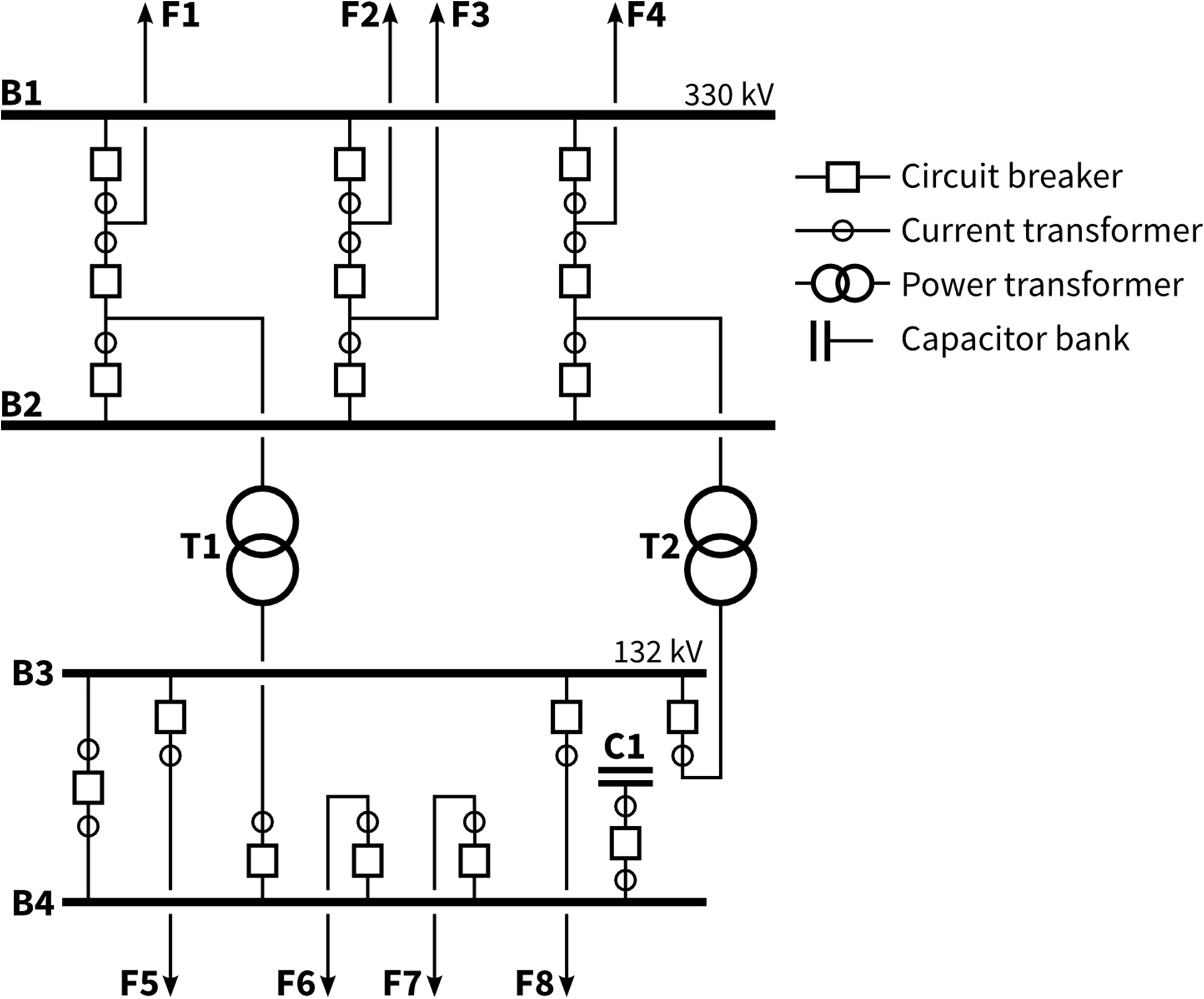
Figure 9: Single line diagram of a 330/132 kV substation with a “breaker and a half” 330 kV switchyard and a folded bus 132 kV switchyard.
Utilities generally take one of two approaches to the design of the substation control buildings: either a single control room with all protection and control equipment inside, or modular control buildings (usually prefabricated off-site) that are placed in the switchyard. This will determine the topology of the Ethernet network and the level of redundancy required. In this example the network is designed so the 330 kV and 132 kV control equipment are installed in separate buildings. For the sake of clarity only some devices are shown in Figure 10. Redundant connections are not used, and only one protection scheme is shown. GE “UR” series relays have been selected for this example as these have built-in PMU functions and support PTP for high accuracy time synchronisation that is required (rather than requiring IRIG-B as most protection relays do). Native support for PTP is also available in protection relays for distribution and industrial applications. This example incorporates a distribution protection relay, the ABB REV615, that has native PTP support for capacitor bank control.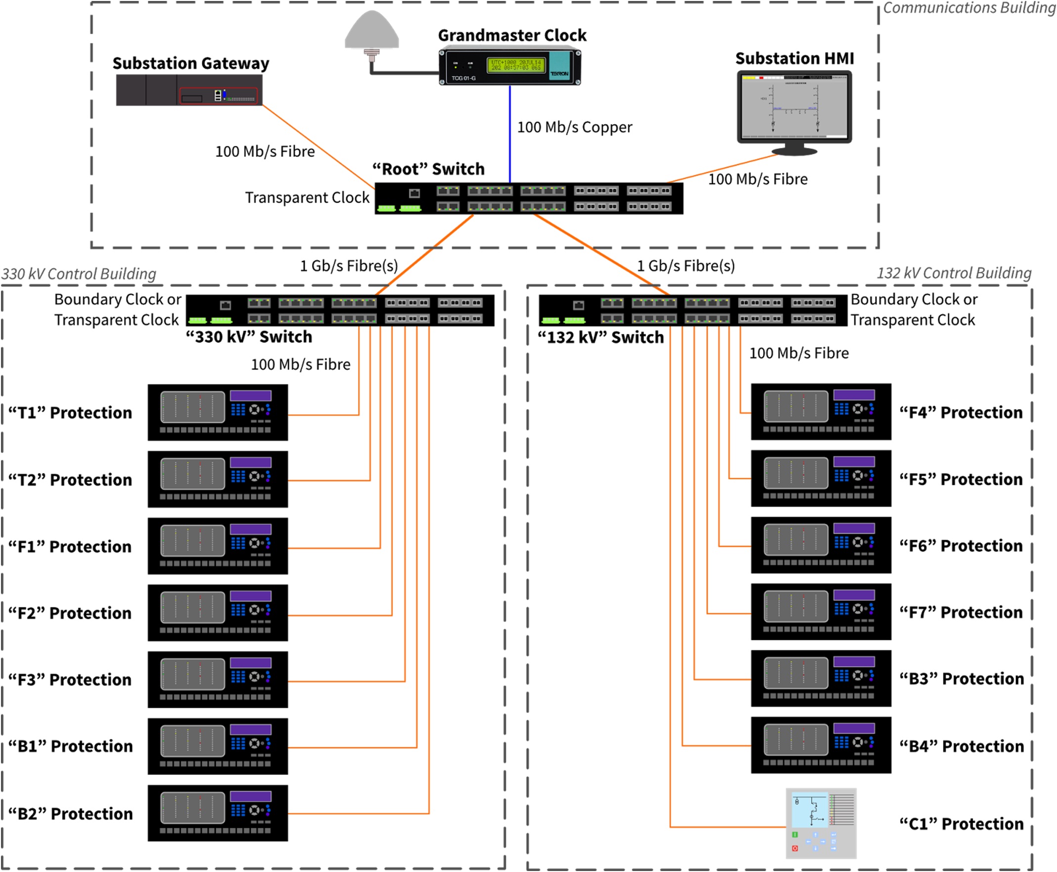
Figure 10: Network topology for 330/132 kV substation with a central communications building and two protection/control buildings.
The primary source of time is the Grandmaster Clock with a satellite receiver. It is recommended that the PTP grandmaster clock is also an NTP master clock, as NTP can be used by automation servers, SCADA gateways, energy meters and protection relays that require millisecond-level accuracy. Ethernet switches are used to distribute PTP message throughout the substation, along with IEC 61850, DNP3, HTTP, SNMP and any other protocols that are used. PTP traffic is so low in volume, approximately 420 bytes per second, that there is no impact on the rest of the network. Figure 11 shows a Wireshark capture of PTP traffic from a Tekron grandmaster clock transmitting one Sync (red), Follow Up (magenta), Announce (blue) and Peer Delay Request (green) per second, and responding with one Peer Delay Response (yellow) and Peer Delay Response Follow Up (tan) per second. This two step mode of operation creates the most PTP network traffic, and so is the worst case.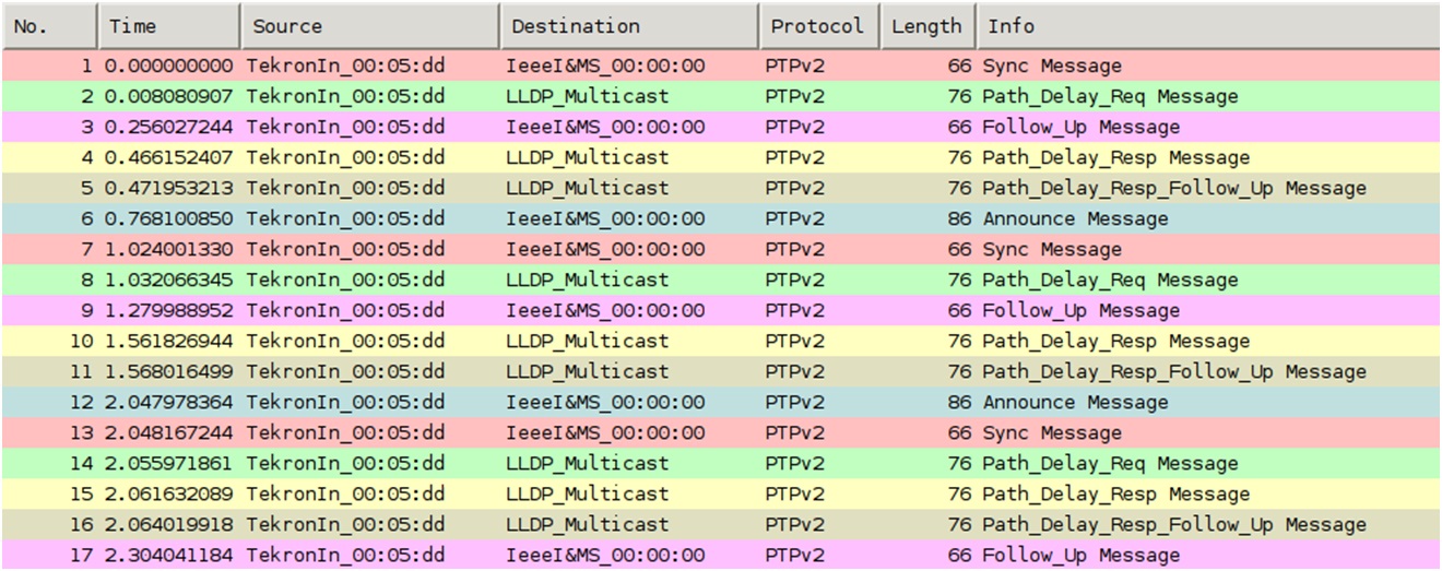
Figure 11: PTP network traffic transmitted by a two step grandmaster clock.
The “Root Switch” is the centre of the substation Ethernet network. This is where “whole of substation” services, such as SCADA gateways (to control centres), operator interfaces (HMIs), security systems and engineering workstations connect to the LAN. In this design there are two additional switches, one each for the 330 kV and 132 kV protection equipment. This reduces the number of Ethernet cables required to communicate with protection relays. Local switches in each control building enables horizontal communication between protection relays (e.g. GOOSE messages for bus zone tripping and CB fail initiation) to remain in service if the network link to the central communications building fails. The number of Ethernet switches used in a network is a balance between:- flexibility: more switches means more ports
- reliability: there is a greater chance of failure of a single switch if more are in service
- robustness: if a switch fails, how many items of HV plant will you lose control of?
3.2. Replacing an IRIG-B distribution system with PTP
There are times where it may be desirable to replace an existing time distribution system or to adopt new technology when extending a substation. This example looks at an extension of a transmission substation where an additional control building is required. The existing substation uses Ethernet for communication with protection relays and uses IRIG-B time codes to synchronise the clocks of the protection relays. Fibre-optic cable is used for both Ethernet and IRIG-B as this provides the best immunity to interference and the safety of galvanic isolation. Isolated Timing Repeaters (ITRs) are used to convert the optical IRIG-B time code signals back to electrical forms that can be used by the protection relays. Figure 12 shows the general arrangement of a 330/132 kV substation prior to its expansion, with the primary equipment, control buildings and communication cabling shown.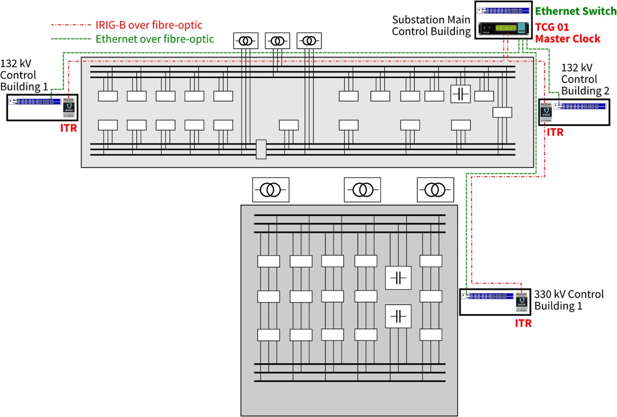
Figure 12: General arrangement of 330/132 kV substation using conventional time synchronisation equipment.
The utility has a project in place to add three more “diameters” of breaker-and-a-half switchgear to the 330 kV switchyard, along with an additional 330/132 kV transformer. Another control building will be installed to house the protection relays and other control equipment. While it would be possible to loop the IRIG-B signal from 132 kV Control Building 1, the total path is long and introduces time error due to propagation delay. This “brownfield” expansion is an opportunity to gain experience with PTP. Very little equipment needs to be replaced. If the GPS master clock cannot support PTP then it must be replaced. The Tekron TCG 01-G selected for this example supports all existing time codes as well as PTP and NTP. If the main Ethernet switch (the “root” switch) does not support the Power Profile then it must be replaced with one that does, such as the GE MultiLink ML3000. The configuration of the old switch should be documented so all VLAN and multicast filter definitions, port configurations and SNMP monitoring settings can be replicated. The final step is to use a PTP Translator in the new control building rather than an Isolated Timing Repeater (ITR). This converts the PTP signal back to IRIG-B (modulated and/or unmodulated), allowing the standard protection design to be used for the expansion. Any Ethernet switches installed in the new control building need to be Power Profile transparent clocks or boundary clocks. Figure 13 shows the layout of the upgraded substation. It is worth checking to see if the protection relays used in the utility’s standard design have been updated by the manufacturer to support PTP. This provides another opportunity to gain experience with PTP without changing tried and tested protection designs.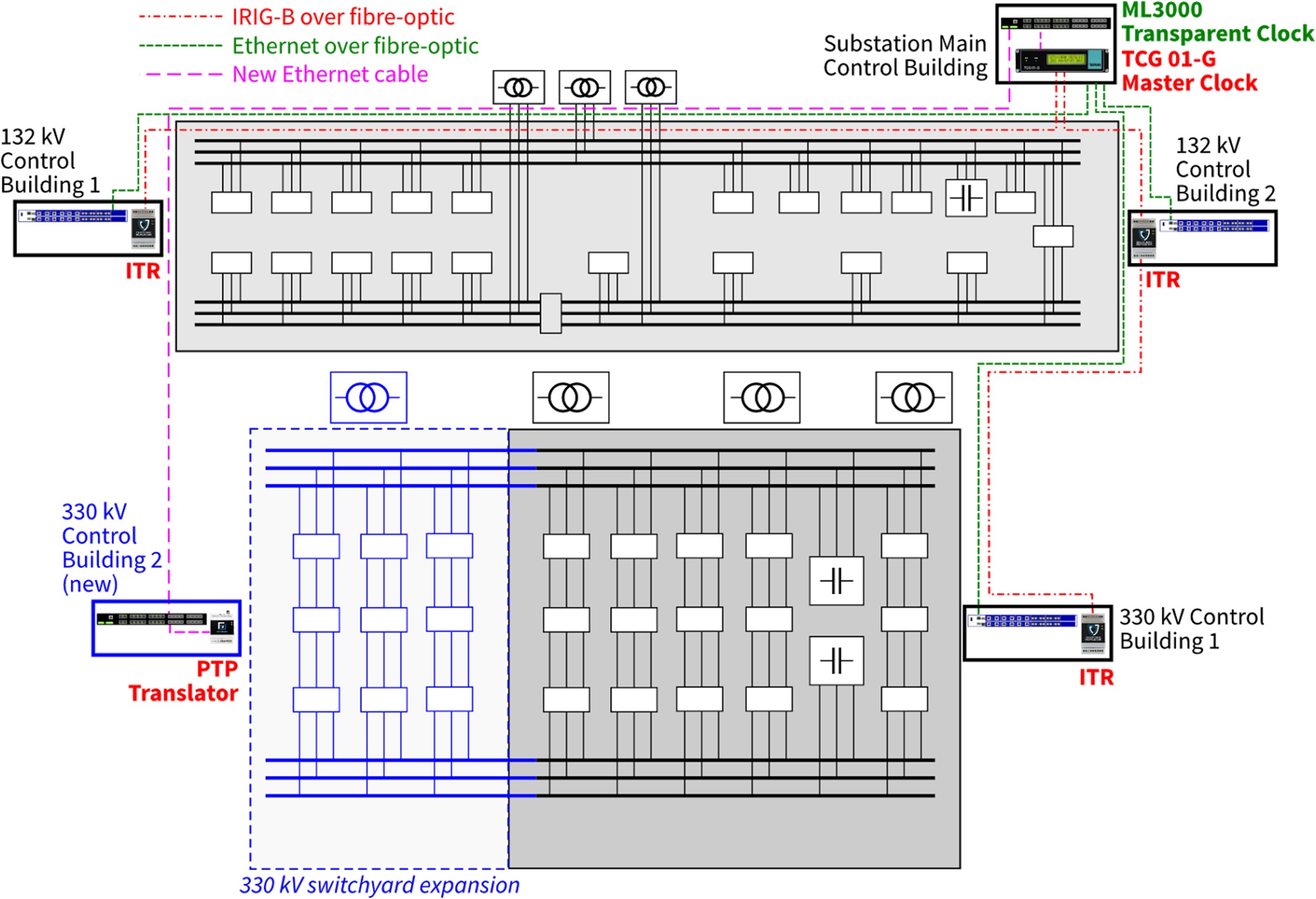
Figure 13: General arrangement of extended substation with an extra transformer, switchgear and control building.
No compensation of propagation delay is needed for devices in the new control building as this is taken care of automatically by the peer-delay mechanism specified by the Power Profile. This simplifies the configuration and commissioning of PMUs and other applications that need microsecond-level accuracy. A refinement to the panel design might be to install a PTP translator in each panel, rather than having inter-panel IRIG-B cabling. Many utilities have adopted the practice of eliminating metallic communications cables between panels, and this can be achieved through the use of PTP over fibre-optic Ethernet—the same Ethernet that is being used to communicate with protection relays. Figure 14 shows conventional time synchronisation with AM and unmodulated IRIG-B time code signals. Ethernet connections to each relay are used for control purposes, however this could be DNP3 or IEC 60870-5-101 over RS485 in an older automation design.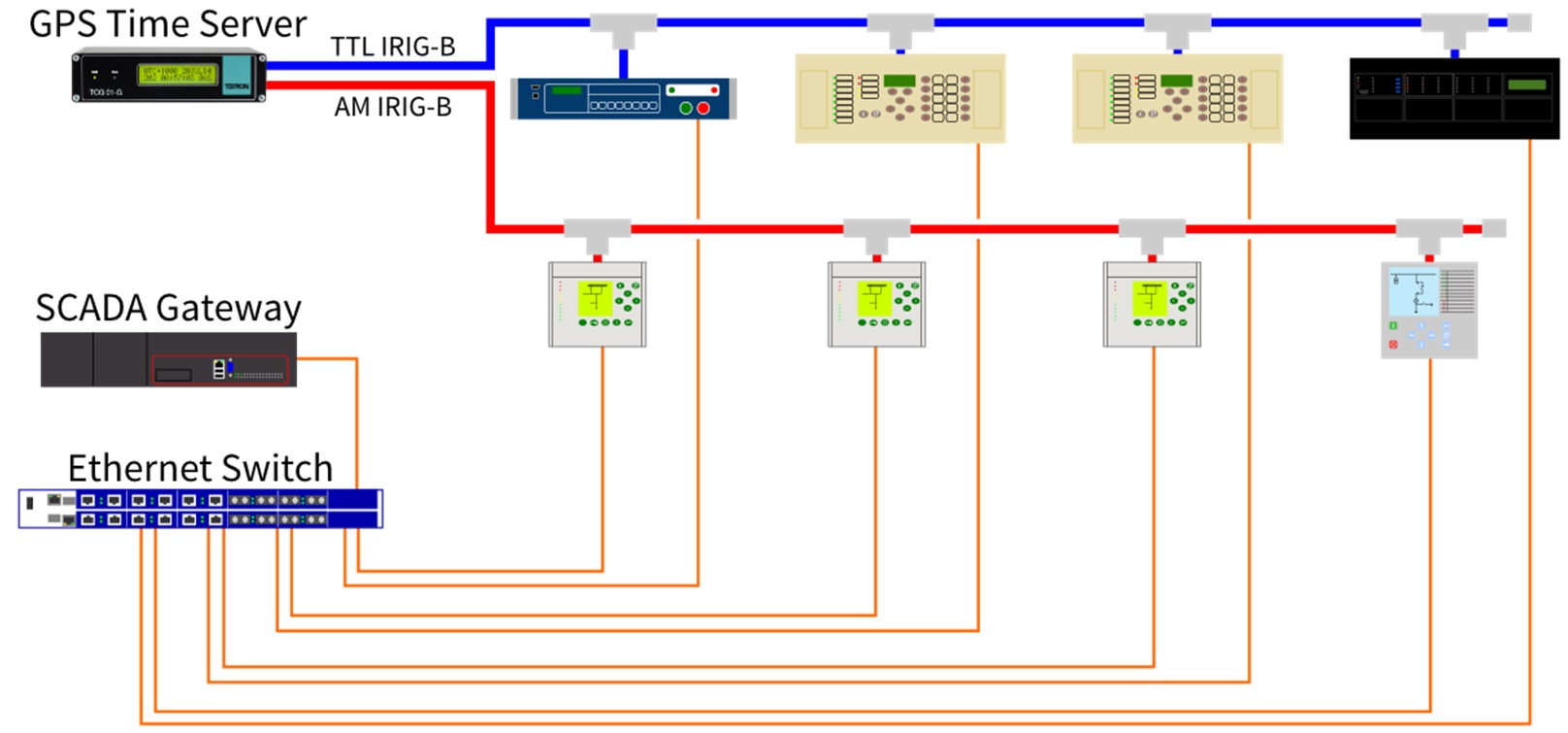
Figure 14: Conventional time synchronisation and communication connections.
The use of PTP for time synchronisation within a substation then allows inter-panel communications to use fibre-optic cable. PTP slave clocks, such as Tekron’s PTP Translator, are used to generate conventional time codes at each panel. Local generation of IRIG-B time codes means that each panel can have a different format or time zone, giving greater flexibility that is currently possible with a single IRIG-B source. Figure 15 shows how PTP can be used to distribute time to existing protection relays with translators and to upgraded protection relays with native support for PTP.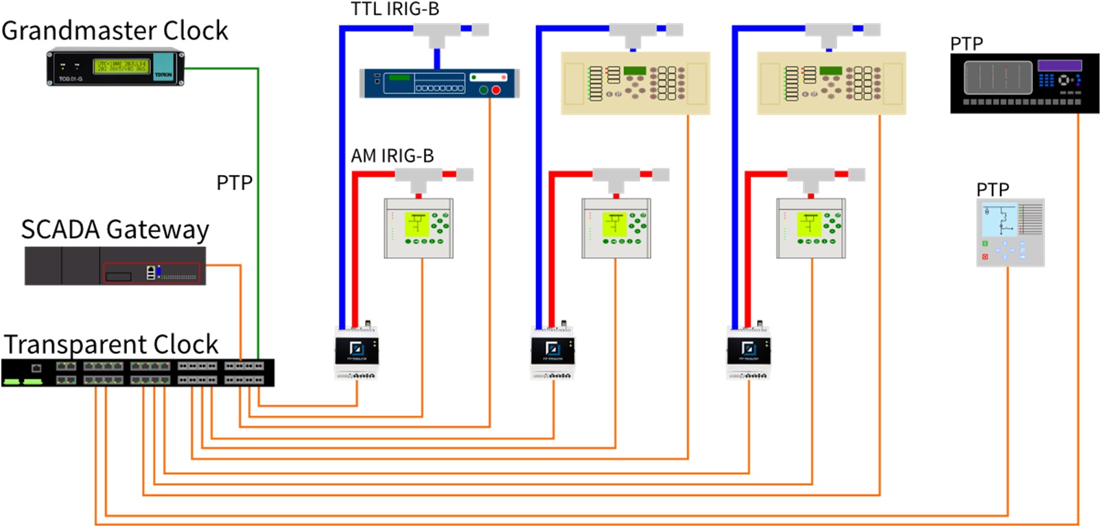
Figure 15: PTP time synchronisation within a substation using a combination of stand-alone slave clocks (PTP translators) and protection relays with built-in support for PTP.
Adopting PTP for brownfield developments gives utilities and system integrators the opportunity to gain experience with PTP in a gradual manner. Having PTP infrastructure in place then provides a test-bed for to evaluate new and revised protection relays that have native support for PTP. If a utility is moving to Ethernet in the substation for the first time then it is prudent to investigate the use of Ethernet switches that support the PTP and the Power Profile. Revisions to protocols can be made through firmware updates in the future, but these are dependent upon having PTP hardware support in the first place.3.3. Network design to support redundancy and PTP
Section 3.1 described the PTP aspects of a network for a new substation. This section presents a design philosophy that supports PTP and can form the basis of a substation LAN. The fundamental principles are:- The failure of any device or network link does not result in the loss of control of more than one bay of HV switchgear.
- Fully redundant duplicate protection is used, often referred to as Main1/Main2, A/B or X/Y protection.
- Switchgear is controlled by one of the protection relays and not through dedicated bay controllers.
- Rapid Spanning Tree Protocol (RSTP) ring or mesh networks. Supported by most, if not all, substation Ethernet switches. The time required for the network to recover following an outage is not defined. Networks can take some time to stabilise, especially if there are meshes rather than rings.
- Parallel Redundancy Protocol (PRP) duplicated networks. No loss of data for a single link or switch failure, and straightforward design. Requires specific support or the use of a “redundancy box” (also called a “redbox”), and an increased number of switches are required.
- High-reliability Seamless Redundancy (HSR) ring networks. No loss of data for a single link or switch failure, and avoids need for extra switches. Is limited to a ring topology and requires specific support by connected devices (e.g. PTP clocks and protection relays) or the use of a redbox to connect non-HSR devices into the ring.
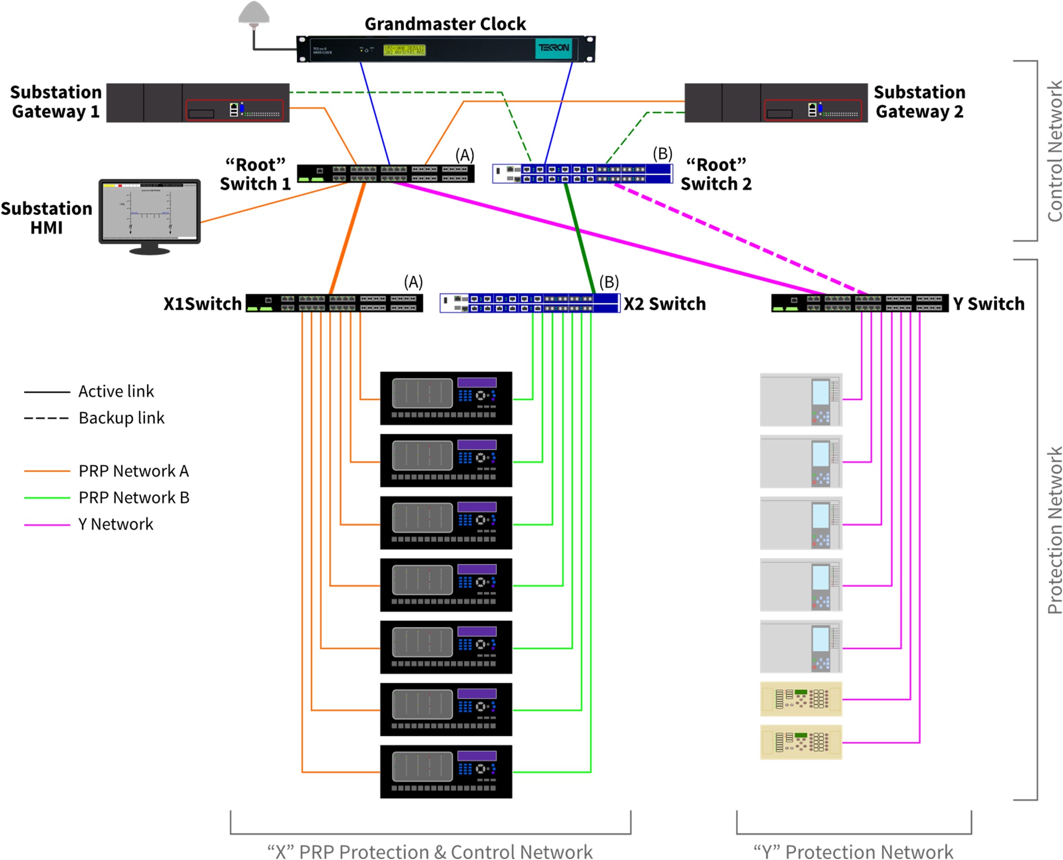
Figure 16: Redundant network architecture using PRP for network control, with duplicate protection systems.
It is expected that substation gateways will eventually support PRP natively, allowing both links to remain active at all times. Similarly, Switch Y could provide “Redbox” (redundancy box) functionality for the Y protection relays, taking care of de-duplication of frames. Substation rated Ethernet switches are now available with high port density, avoiding the need for “breakout” switches in relay panels. In smaller substations the protection switches (X1, X2 and Y in the figure above) may not be required, and conversely in large substations it may be useful to have a set of X1, X2 and Y switches for each voltage level. Regardless of the topology, the use of Ethernet switches with PTP transparent or boundary clock capability will allow PTP clients to be connected at any location in the network. 4. Conclusion An Ethernet network-centric design for substation protection and control reduces costs for design, construction and maintenance. The Precision Time Protocol, particularly when used with the Power Profile, overcomes many of the time synchronisation difficulties faced in substation automation systems and is consistent with the design trend for Ethernet-based substation communication. Tekron has over ten years’ experience building time synchronisation products for the power industry. Tekron’s range of PTP clocks and support devices have been built primarily for use in substations, not as an after thought. This experience has been used to create a range of PTP products that enable utility and industrial customers to develop timing designs using modern protocols and technology, while maintaining compatibility with tried-and-tested methods. 5. References- D.M.E. Ingram, P. Schaub, D.A. Campbell & R.R. Taylor, “Evaluation of precision time synchronisation methods for substation applications”, 2012 International IEEE Symposium on Precision Clock Synchronization for Measurement, Control and Communication (ISPCS 2012), San Francisco, USA, 23-28 September 2012. Available from http://eprints.qut.edu.au/53218/.
- D.M.E. Ingram, P. Schaub, D.A. Campbell & R.R. Taylor, “Quantitative assessment of fault tolerant precision timing for electricity substations”, IEEE Transactions on Instrumentation and Measurement, October 2013. Volume 62, Issue 10, pp 2694-2703. Available from http://eprints.qut.edu.au/56835/.